Cabarrus Amateur Radio Society

Cabarrus County, Concord, NC


Low Loss Coax for Pocket Change
A Measured Look at Browning BR-200 Coax
An inexpensive spool of Browning BR-200 coaxial cable led to an unexpected engineering evaluation of its construction and RF performance. Laboratory measurements suggest that this low-cost RG-58-size feedline delivers surperior attenuation, shielding, and power-handling characteristics for HF and VHF amateur radio applications.


The Typo That Wasn't
Life in amateur radio can be funny. Sometimes the best discoveries happen entirely by accident.

A little while back, while shopping for a dual-band VHF/UHF vertical antenna, I ended up browsing the website of
Buy Two Way Radios. Based in South Carolina, the company carries a respectable assortment of both commercial and amateur radio gear. After comparing several antennas from Comet and Tram, I wandered into the coax section looking for anything interesting.


That is where I stumbled across something that immediately caught my attention: a 500-foot spool of Browning BR-200 “Low Loss” 50-ohm coaxial cable for $35 plus shipping, roughly ten cents per foot. Sitting right beside it was a comparable spool of RG-8X priced around $120.

My first thought was simple: that has to be a typo. It was not!

The published specifications for the Browning BR-200 were surprisingly ambitious for a cable in that price range:

  • 50-ohm impedance
  • Low Loss
  • RG-58-size diameter
  • Velocity factor: 83%
  • Shielding effectiveness: >90 dB

The published attenuation chart claimed nearly half the loss of standard RG-58/U, with substantially greater power-handling capability, all while maintaining the same overall size. Two specifications immediately stood out: 83% velocity factor and the excellent >90dB shielding figure.

Those numbers strongly suggested two things:

  • The dielectric was almost certainly gas-injected foam polyethylene rather than the solid polyethylene used in traditional RG-58/U.
  • The cable likely employed a dual-layer shield consisting of bonded aluminum foil beneath a braid, rather than braid alone.

With a tinned copper shield, solderable construction, and a solid 1.2 mm center conductor (18AWG), the cable looked interesting enough to justify the gamble. At roughly $50 shipped for more than 500 feet, it was difficult to ignore. Frankly, you can barely buy decent antenna wire for that price anymore.

Further digging revealed that the BR-200 is essentially a Chinese-manufactured equivalent to LMR-200, with specifications closely resembling the well-known cable. On paper, it outperforms standard RG-58/U in nearly every engineering metric, including attenuation, shielding effectiveness, velocity factor, and UV resistance.

Unfortunately, Buy Two Way Radios was sold out, but additional stock turned up at
Max Marine Electronics Inc. in Florida. Two days later, a 508-foot spool arrived at my doorstep.

At the time, I did not actually need more coax. Most of my permanent antenna installations already use LMR-400-class cable. My intent was always to use this line for experimental antenna testing, where I can easily eliminate its electrical effects by calibrating the VNA right up to the antenna feedpoint. Plus, an extra spool of coax is always a welcome asset around the lab for general use.Still, being both an engineer and naturally skeptical, I decided the newcomer deserved a proper evaluation.

The cable arrived on a sturdy wooden spool. Right away, it was apparent that the BR-200 is somewhat stiffer than RG-58/U. That is not surprising given its solid 18 AWG bare copper center conductor, compared to the smaller 20 AWG stranded conductors commonly found in RG-58 variants.

Today, Browning itself is an Oklahoma-based distributor associated with the long-running Tram-Browning brand names. In an interesting historical twist, purchasing BR-200 today effectively means buying a modern Chinese-manufactured low-loss foam dielectric cable carrying a brand name that traces its roots back to the early vacuum tube era and Browning Laboratories of Winchester, Massachusetts.

Initial Evaluation
Curious about the internal construction, I cut a sample section apart for inspection. My original assumption proved correct: the cable uses a bonded aluminum foil shield beneath a layer of tinned copper braid.


One detail immediately stood out. Unlike some inexpensive imported coaxial cables, the bonded foil layer was firmly adhered to the dielectric core, and not at all easy to peel off. That matters. Poorly bonded foil shields can shift under repeated bending, causing localized impedance variations and degraded long-term consistency. The BR-200 sample appeared mechanically solid and surprisingly well executed.

The bonded foil also serves as an effective secondary moisture barrier, provided it is properly manufactured and adhered. In this case, it appears to be.

Sidebar: Why Shielding Effectiveness Matters
Today’s homes are filled with broadband electrical noise sources: switching power supplies, LED lighting, solar inverters, Ethernet devices, plasma televisions, battery chargers, and countless microprocessor-controlled appliances. Poorly shielded coaxial cable can allow this noise to leak directly into a receiving system — or permit transmitted RF energy to escape from the feedline itself.

Shielding effectiveness, usually expressed in decibels (dB), measures how well a cable prevents unwanted RF leakage both into and out of the cable. Traditional single-braid RG-58 cables often provide shielding effectiveness in the 40–60 dB range. Modern dual-shield cables using bonded foil plus braid commonly exceed 90 dB.

That difference can be dramatic, particularly at VHF and UHF frequencies or in high-noise suburban environments. Better shielding reduces received interference, minimizes RF leakage inside the shack, and improves immunity to locally generated electrical noise.

In practical terms, a well-shielded coaxial cable does more than simply carry RF power efficiently, but it also helps preserve signal integrity in an increasingly noisy world.


I also found myself appreciating the solid 18 AWG center conductor. Yes, it sacrifices some flexibility, but electrically it offers lower resistance, better dimensional stability and more consistent impedance geometry than cheaper stranded alternatives.

Measurements
With the physical inspection complete, it was time for the real test: RF attenuation.

Fortunately, both ends of the factory spool were accessible, allowing measurements through the entire 500-foot length for maximum accuracy. To minimize connector-related uncertainty, SMA connectors were carefully soldered onto both ends of the cable.


Measurements were performed using an HP 8753C vector network analyzer. I briefly considered using a NanoVNA-H4, but expected UHF losses over 500 feet to exceed the practical dynamic range and accuracy limits of a low-cost handheld instrument.


From the outset, the data clearly indicated that this cable is best suited for HF and perhaps short VHF runs. Due to high insertion loss at UHF frequencies, it is impractical for anything other than very short runs, patch lines or jumpers.

After calibration from 1 to 500 MHz (going beyond 150MHz is somewhat academic for this cable class), a s21 sweep was performed of the entire 508ft spool. The measured insertion loss was then normalized to the standard 100-foot reference length, and is reported below. The cable's practical operating range is realistically limited to frequencies below the 2-meter band. Beyond that threshold, insertion loss escalates to a point where further performance analysis becomes purely academic.


Even at 2m, high attenuation limits usage to short runs of around 20 feet, restricting it to mobile applications. However, performance at HF is excellent, decent at 6m, with the cable truly excelling on the low bands. On 80m, for example, a 300-foot (100m) run yields only 1 dB of loss, and 160m equally reaches 500ft.

Insertion loss within the 70-centimeter band was measured at 9.6 dB per 100 feet. While this outperforms standard RG-58U, it remains impractical for infrastructure runs, delivering only about 10% of the input power to the antenna.


I also measured characteristic impedance using a carefully prepared 3-meter sample. The result was 50.3 ohms, an impressively close match to nominal 50-ohm impedance, better than many inexpensive RG-58 variants I have tested over the years.

Sidebar: Why 50 Ohms?
The answer turns out to be a compromise dating back to the early days of RF power transmission. Engineers discovered that coaxial cable impedance affects both power-handling capability and attenuation loss — but the two do not reach their optimum values at the same impedance.

For air-dielectric coaxial lines:
  • Maximum power handling occurs around 30 ohms
  • Minimum attenuation occurs around 75 ohms

As radar and radio technology rapidly evolved during World War II, engineers settled on 50 ohms as a practical middle ground between low loss and high power capability. The result was a cable impedance well suited to transmitters, antennas, and military RF systems.

That compromise survived the vacuum tube era, the transistor revolution, and into modern wireless communications. Today, 50 ohms remains the standard impedance for most amateur radio, commercial RF, laboratory, and test equipment, while 75-ohm cable is still commonly used where low loss matters more than power handling — such as television and receive-only applications.


Measured velocity factor ranged from approximately 0.81 to 0.84 depending on frequency, closely matching the published specification. Cable capacitance measurements were likewise very close to the manufacturer’s published data.

Power-handling capability was briefly evaluated at 30 MHz using a 10-foot sample feeding a UHF dummy load. Measured VSWR remained essentially perfect at 1.01:1. Using an Ameritron AL-1200 amplifier, the cable handled over 1500 watts without issue. Using a small IR spot thermometer intended for SMD thermal measurements, I observed only about a 5 °C temperature rise — noticeable, but hardly alarming. For reference, the published 30MHz specification lists 1200 watts maximum power handling.

Repeating the same test at 3.5 MHz produced no measurable temperature rise at all that I could observe. With the possible exception of heavy-duty 10-meter service, I see little reason this cable could not handle 1kW HF operation in most amateur applications. But, as with any coaxial cable, elevated VSWR conditions will reduce practical power-handling capability. I would exercise considerable caution before using it for legal limit QRO operation.

At this point, the inexpensive BR-200 stopped looking like bargain-bin coax and started looking like a genuinely useful low-loss alternative for many HF amateur radio applications.


Using my own measurements, observations, and the published specifications I considered trustworthy, I assembled an informal working datasheet for the cable:

Conclusion
An accidental discovery ultimately led to a surprisingly capable coaxial cable at an almost absurdly low price. For HF service, the BR-200 appears perfectly suitable for feedline runs in the 100–200 foot range. The cable also performs respectably on the 6-meter band and is suitable for short, mobile-length runs on 2 meters, though shorter runs are inherently preferable as operating frequencies ascend. However, due to excessive attenuation, this cable is entirely non-viable for 70 cm applications.


In the end, the Browning BR-200 turned out to be far more than just another bargain-bin import coax. While no one would mistake it for premium hardline or top-tier commercial feedline such as LMR-400, the measured performance tells a very different story than the price tag suggests. It is essentially a budget-friendly equivalent to LMR-200, matching its performance profile without the associated cost. Its low HF attenuation, excellent shielding, stable impedance, and surprisingly solid construction place it far above the level traditionally associated with inexpensive RG-58, RG-8X, and similar cable classes.

Perhaps most importantly, this little experiment serves as a reminder that hidden among the endless stream of rebranded products and marketing hype, there are genuinely worthwhile discoveries waiting to be found. The BR-200 may not carry the prestige (or the price) of more established names, but based on both measurement and inspection, it earns its place as a practical and economical option for many amateur radio applications.

Not every accidental discovery in amateur radio turns into something useful. This one did.

Why Coaxial Cable Is Called “Coax”
The term coaxial cable comes from the fact that both conductors share the same geometric axis. A central conductor is surrounded by an insulating dielectric, which is itself enclosed by a tubular outer conductor or shield. Because the two conductors are perfectly aligned, or co-axial, the cable contains most of its electromagnetic field internally.

That geometry is what makes coax so useful at radio frequencies. Unlike open-wire feedlines, coaxial cable radiates very little energy and is comparatively immune to nearby electrical noise. It also maintains a controlled characteristic impedance, typically 50 or 75 ohms, which allows RF energy to travel efficiently from transmitter to antenna.

Modern coax traces its roots back to the 1930s and rapidly became essential for radar, military communications, broadcast systems, and eventually amateur radio. During World War II, huge advances in coaxial cable technology were driven by radar development, particularly the need for low-loss microwave transmission lines.

Even today, despite the rise of fiber optics and digital networking, coaxial cable remains one of the most practical and efficient methods of transferring RF power over short and medium distances, especially in amateur radio stations.


This article is reprinted with permission of the author, Christopher Krstanovic - AI2F.
About Author
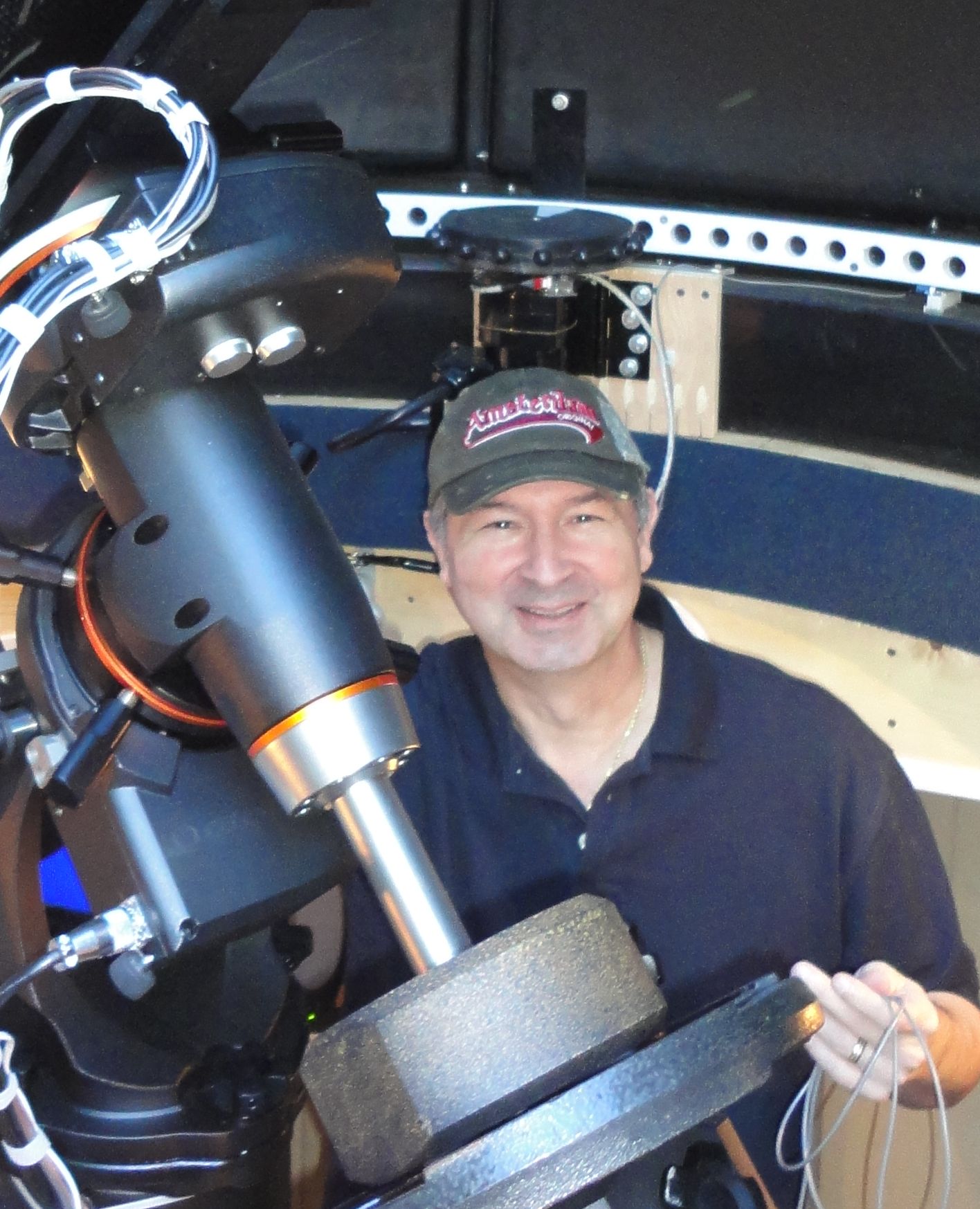
Christopher Krstanovic, AI2F, is a lifelong amateur radio operator, first licensed in the US in 1980s as WR1F. He holds degrees in Physics and a PhD in Electrical Engineering, and his career has spanned corporate engineering as well as technology entrepreneurship. After leaving corporate America, he founded and led three companies before returning to active amateur radio under his current call sign. His operating interests include HF, antenna design, practical radio engineering, Astronomy.

Copyright 2026 © Cabarrus Amateur Radio Society. All Rights Reserved.