Cabarrus Amateur Radio Society

Cabarrus County, Concord, NC


Giving Kenwood TS-780 a 0.6 dB NF
This work summarizes the improvement of a 1985 Kenwood TS-780 VHF/UHF transceiver with an original receiver noise figure of ~10 dB. A Mini-Circuits PSA4-5043+ MMIC was implemented as a compact dead-bug LNA with a simple LC input match, achieving ~0.6 dB standalone noise figure. When placed ahead of the receiver, system noise figures improved to ~0.85 dB on 2 m and ~1.0 dB on 70 cm, verified using an HP 8970B. The results demonstrate the effectiveness of modern MMIC preamplification in significantly upgrading legacy receiver performance, with future work targeting PGA-103+ based designs and further filtering for sub-0.6 dB EME-class sensitivity.


The Sunday Afternoon Itch
Every bench engineer and homebrewer knows the feeling. You walk into the shack intending to fix a minor mechanical glitch, and three hours later you’re knee-deep in laboratory test equipment, dead-bugging surface-mount components under a microscope, and pushing forty-year-old hardware to the absolute limits of physics.

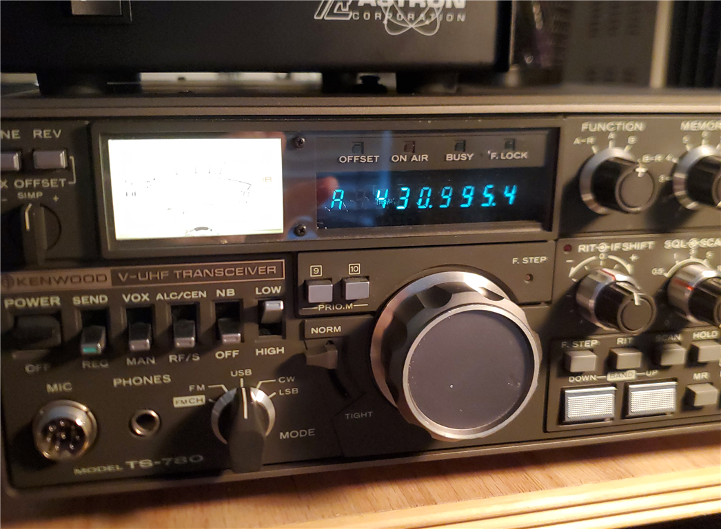
This particular rabbit hole started with a classic: a Kenwood TS-780 dual-band (2m/70cm) multi-mode transceiver.


Dating back to 1985, this was an exceptionally premium, expensive rig in its day—a true flagship of the era. Beautifully constructed, but by modern standards, its receiver is deaf. With a stock noise figure (NF) hovering somewhere around a dismal 10 dB, it is practically useless for any serious weak-signal or tropospheric DX work today.

My initial goals were purely cosmetic and maintenance-driven:
  1. The VFO Glitch: The rotary encoder was intermittently missing counts, especially during slow tuning. Opening up the optical encoder assembly revealed a simple fix—just a delicate adjustment of a couple of internal trimmer potentiometers to restore the proper quadrature waveforms.
  2. The Incandescent Glow: While the covers were off, I pulled out the tired, hot, burned-out S-meter incandescent bulb and retrofitted a modern COB LED array. The result? A perfectly bright, uniform display that runs completely cool.

With the radio working fine, it should have gone back on the shelf. But the test gear was warmed up, the bench was messy, and boredom set in. It was time to play.

Vintage Profile: The Kenwood TS-780 (1980s era)
When Kenwood introduced the TS-780 in the mid-1980s, it was a tour de force of amateur engineering—a heavy, premium, all-mode dual-band transceiver designed for the serious VHF/UHF operator. It featured a true dual-channel design, a beautifully bright vacuum fluorescent display, and premium mechanical construction.

However, the state of the art for consumer RF semiconductors in 1985 meant that broadband receivers typically suffered from high internal thermal noise. A stock noise figure of 10 dB was entirely standard for the era.


The Ten-Minute LNA
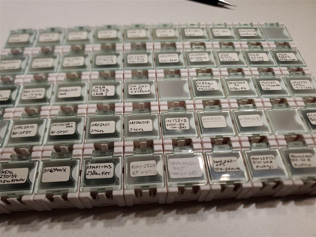
I happened to have a handful of Mini-Circuits PSA4-5043+ low-noise amplifier (LNA) MMICs lying around the shop. These are fantastic, high-linearity, ultra-low-noise pHEMT devices that operate up to 4 GHz.


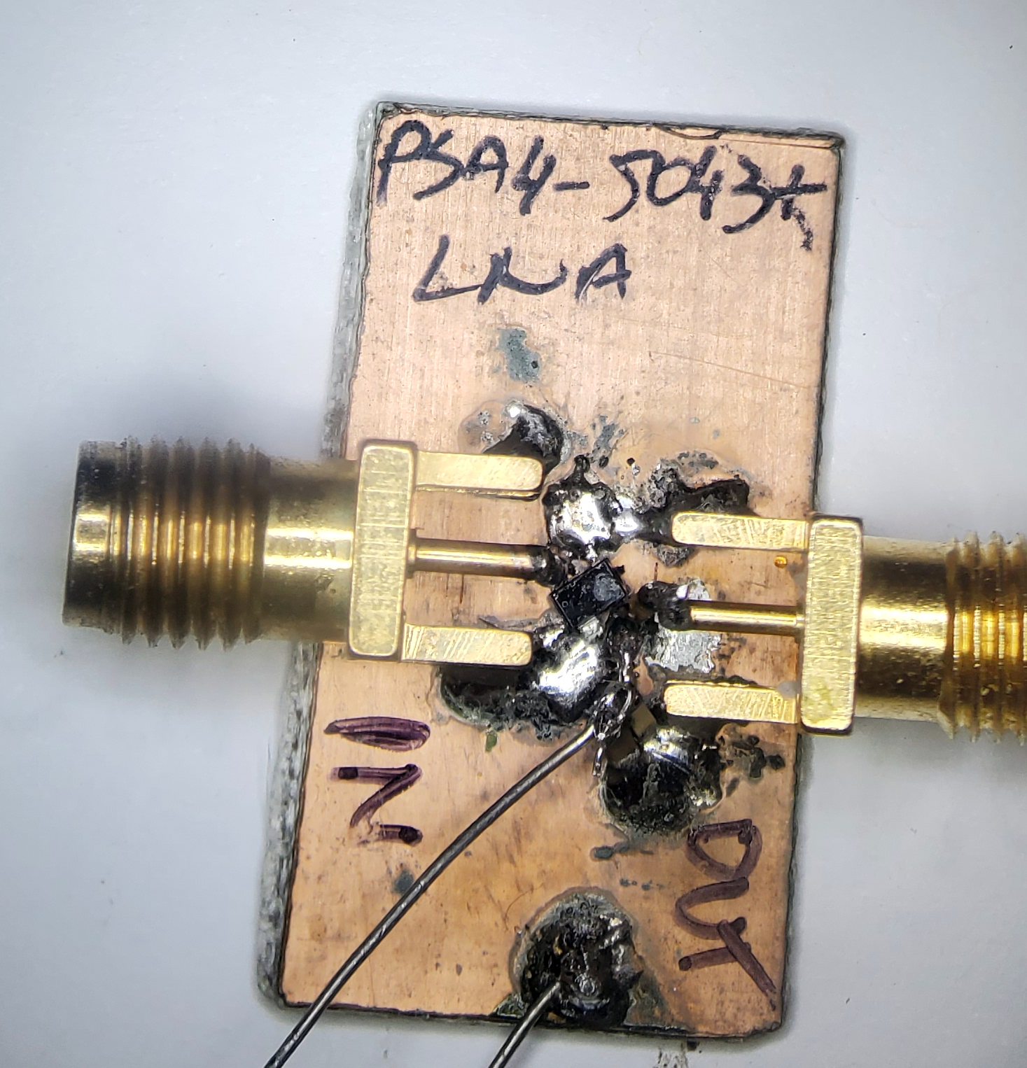
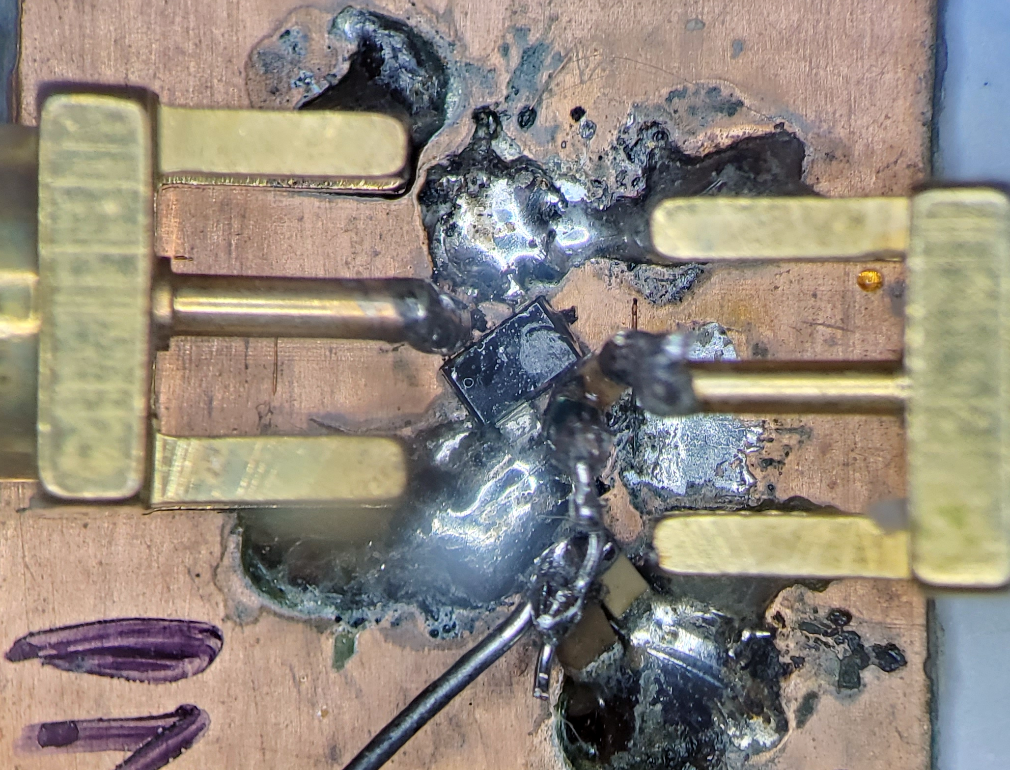
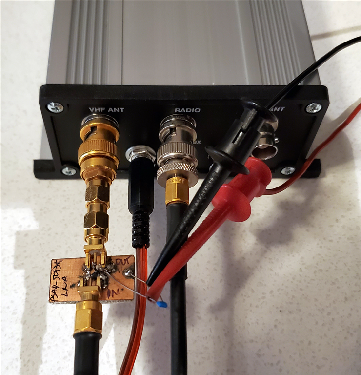
I cut a small scrap of double-sided copper-clad PCB and "dead-bugged" the MMIC and couple of SMA connectors directly onto the ground plane, throwing together a functional LNA circuit in about ten minutes flat.


To see what the raw circuit could do, I fired up my HP 8970B Noise Figure Meter. Measuring the unoptimized board yielded a noise figure of roughly 0.7 dB. Frankly, waiting for the HP 8970B to calibrate took longer than actually building the LNA.


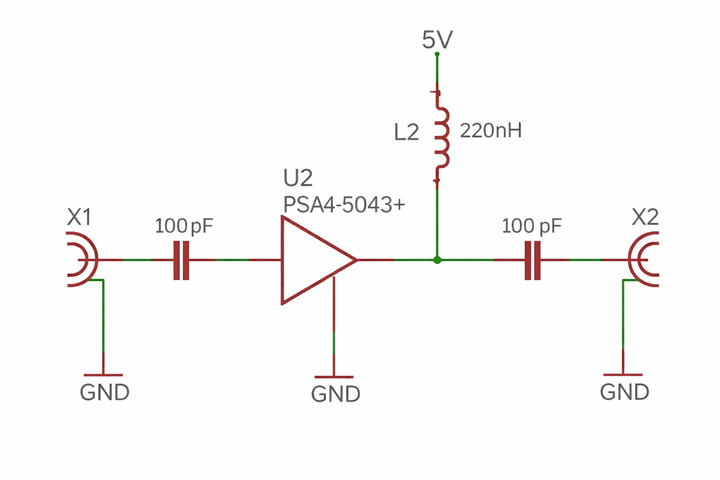
NOTE: GND is Dead-bugged to copper plane

The initial layout didn't include an input matching network for optimum noise figure, so I went back to the microscope. It required only two discrete components—an ordinary 0603 inductor and a 0402 capacitor. Nothing exotic. With the match optimized for 2 meters, the LNA's standalone noise figure dropped to 0.6 dB - every bit counts. Later, I modified the matching network network for 70 centimeters to account for the different impedance characteristics at 432 MHz with simila improvement results.

The System Results: "WOW"
Running the LNA from a clean 5V supply (best OIP3) directly ahead of the legacy Kenwood antenna jack, I measured the overall system noise figure. The results speak for themselves:

  • 2 Meters: ~0.85 dB system NF
  • 70 Centimeters: ~1.0 dB system NF

Note on Metrology: I used a 5 dB ENR noise source and monitored the receiver's audio output to verify this. While not a pristine, isolated, standards-grade laboratory measurement, it was more than accurate enough to confirm that the improvement was massive.

The real test, of course, was on the air. Simply plugging a short, random piece of wire into the antenna jack revealed signals that were completely non-existent on the stock radio. Beacon that previously registered as barely detectable, sub-audible no deflections on the S-meter were suddenly solid, copyable, and crystal clear.

Pushing Into EME Territory
Am I going to use a TS-780 as my primary VHF/UHF weak-signal rig? Of course not! It is fun using it though.

But now that the proof of concept is sitting on my bench, the engineering itch has taken over. I can’t resist the temptation to permanently modify the radio internally.

For the permanent installation, I plan to build two independent LNA chains—one per band, and both dead-bugged and installed within the TS780, just ahead of its own LNAs. OK, so it will take 30 minutes to make it. This time, I’ll opt for Mini-Circuits PGA-103+ MMICs. The goal is an overall system noise figure of roughly 0.6 dB with approximately 25 dB of raw gain, but more importantly 45 dBm OIP3.

By comparison, replacing the frontend's heavy lifting with a modern surface-mount MMIC yielding a 0.6 dB noise figure represents an improvement in sensitivity of nearly 100 times, proving that legacy mechanical craftsmanship can be beautifully paired with modern solid-state physics.

Injecting 25 dB of gain ahead of an old 1980s front end would absolutely require high-Q post-LNA bandpass filtering, particularly on the 2-meter band, to keep the radio's mixer from choking on out-of-band commercial broadcast signals. Fortunately, the PGA-103+ features an Output Third-Order Intercept Point (OIP3) of +45 dBm, making it remarkably robust and incredibly difficult to overload. The TS-780 on the other hand already has helical Toko filters ahead its own LNA (thus, its 10 dB noise figure), eliminating the need to add my own. At that performance tier, this legacy rig enters legitimate EME (Earth-Moon-Earth) sensitivity territory.

Bench Testing the Transverter
I also decided to test the standalone PSA4-5043+ LNA ahead of my Ukrainian made 2-meter transverter, I bought used on qth.com. It already boasts a respectable native 1 dB noise figure.


Instead of re-calibrating the noise figure meter (which I had already turned off), I opted for a classic Minimum Discernible Signal (MDS) test (seeking a 6 dB signal-plus-noise to noise ratio).

  • At a standard 2700 Hz SSB bandwidth, the system was reaching just shy of -140 dBm.
  • Switching the IF down to a narrow 250 Hz CW bandwidth, the signal dropped so deep into the grass that I had to chain additional external step attenuators ahead of the LNA to increase the attenuation and prevent signal leakage around the shielding. Without an fully isolated screen room, it's hard to verify a definitive number at that level—but we were safely hovering somewhere around -150 dBm.

To truly optimize this transverter setup, the next logical step is moving the LNA to the masthead. Introducing a high-linearity device like the PGA-103+ (0.5 dB NF), or a state-of-the-art SAV-541+ with its remarkable 0.2 dB noise figure right at the antenna, would instantly eliminate feedline losses and provide a massive boost to overall system sensitivity, and fundamentally transform this transverter-based station's ultra weak-signal performance..

It is amazing what a spare millimeter-sized chip, a piece of scrap copper board, and a boring Sunday afternoon can do for the junk box. Keep your soldering irons hot, look past the old specifications sheets, and never underestimate the power of a modern MMIC!

The Verdict
At the end of the day, that is the real beauty of amateur radio. In an era where modern technology is completely sealed, surface-mount-disposable, and entirely automated, we still have the freedom to grab a piece of scrap copper board, heat up the soldering iron, and fundamentally rewrite the specifications sheet of a classic radio.

Ultimately, this experiment proves that legacy VHF/UHF multi-mode transceivers do not need to be relegated to the back shelf just because of their dated semiconductor architecture. By taking advantage of modern pHEMT MMICs like the PSA4-5043+ or the PGA-103+, we can easily bypass the severe thermal noise limitations of 1980s front ends.

My Kenwood TS-780 may have started the day as an archaic, deaf shelf decoration, but it leaves the bench as a high-linearity, weak-signal-capable thoroughbred.

It was a spectacular way to cure a boring Sunday afternoon. If you have an old rig gathering dust in the closet, stop reading, fire up the bench, and see what a little modern silicon can do.

This article is reprinted with permission of the author, Christopher Krstanovic - AI2F.
About Author
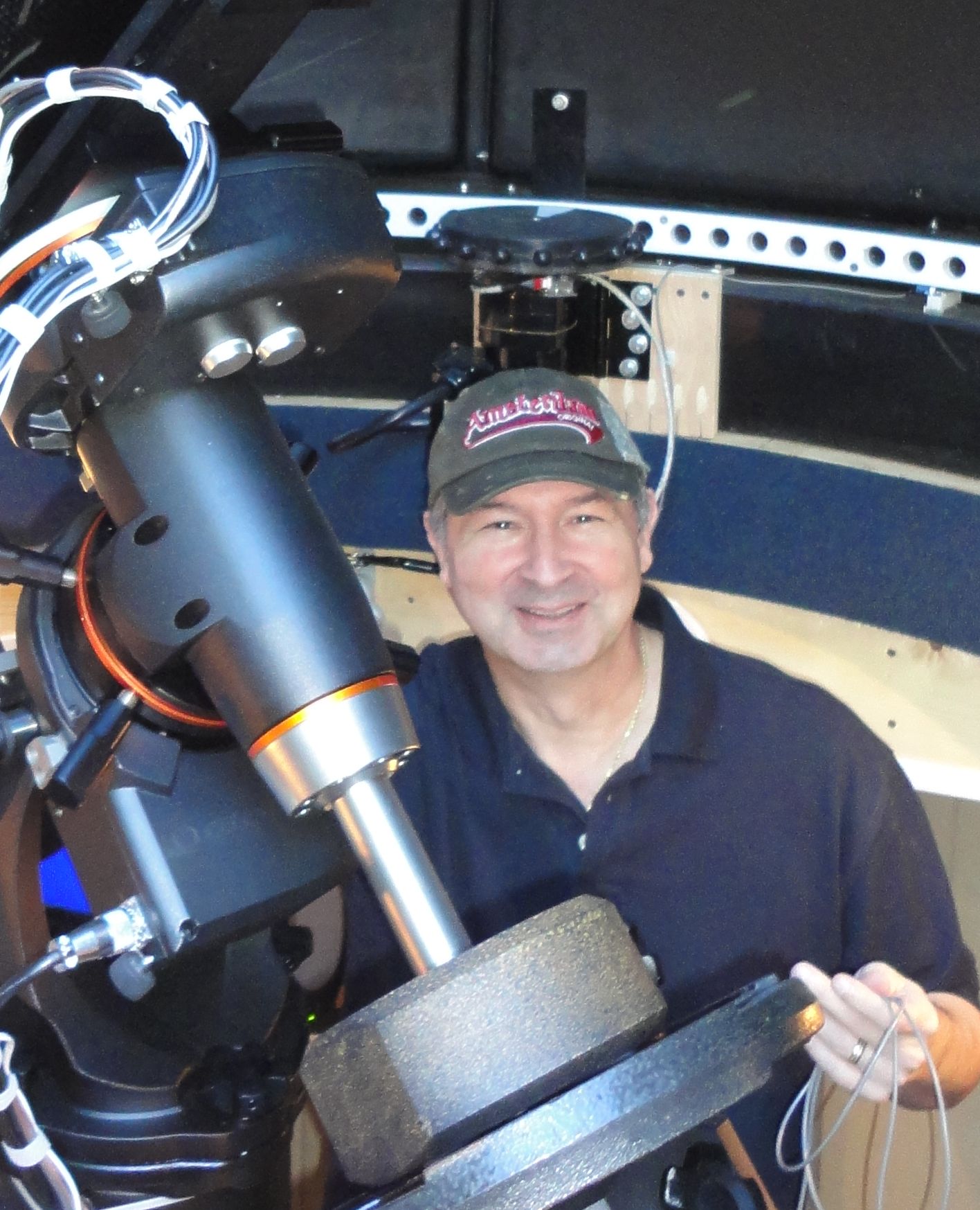
Christopher Krstanovic, AI2F, is a lifelong amateur radio operator, first licensed in the US in 1980s as WR1F. He holds degrees in Physics and a PhD in Electrical Engineering, and his career has spanned corporate engineering as well as technology entrepreneurship. After leaving corporate America, he founded and led three companies before returning to active amateur radio under his current call sign. His operating interests include HF, antenna design, practical radio engineering, Astronomy.

Copyright 2026 © Cabarrus Amateur Radio Society. All Rights Reserved.